On site

Installing multipart covers

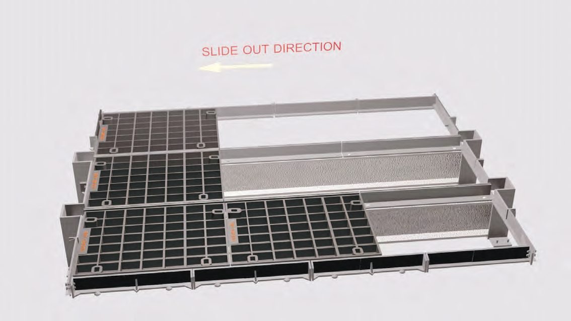
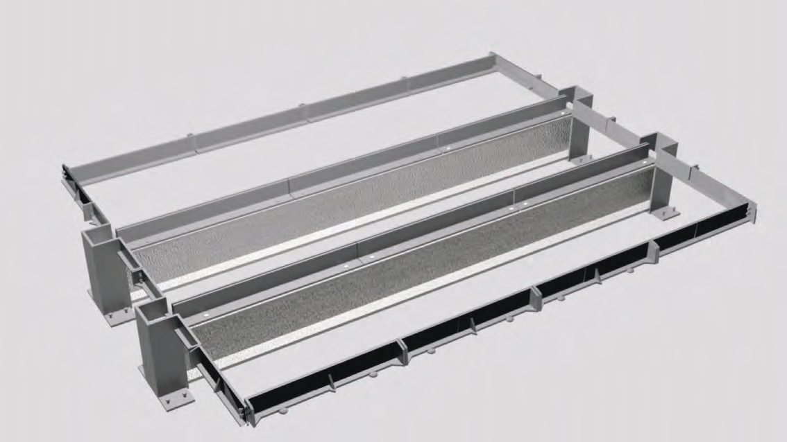
Multiple slide-out covers and frames are supplied with or without removable I-beams, built to the dimensional requirements of the pit opening. The following is general guidance — unit-specific installation drawings are issued with every order.

Pre-installation assembly

  1. Frame parts are supplied dismantled and set-marked for transport. Assemble them at site in the marked sequence.
  2. Place all connected parts in the pre-built rebate with the I-beam holder in the pre-built wallbox rebate. For larger units, assemble at the pit rebate itself.
  3. Drop the I-beam / L-angle assembly one by one into the I-beam holder and check the frame top is flush with the top of the rebate all round.
  4. Pack sufficient spacers under the frame parts so the frame top is flush with the rebate, checked against a string line. Use steel or cement sheet — spacers that will not crumble under the frame weight.
  5. All frame cover seating areas must be flush, linearly aligned and spirit levelled.
  6. Check that the inner opening length of the frame at the top is equal when measured diagonally in both directions.
  7. Ensure the I-beam holder seating does not protrude into the clear opening and stands at 90° to its base.
  8. Use rigid wedge spacers between the frame parts and the rebate wall to prevent the frame twisting.
  9. Clean all debris from every vertical seating section of the frame parts.

Installing the covers

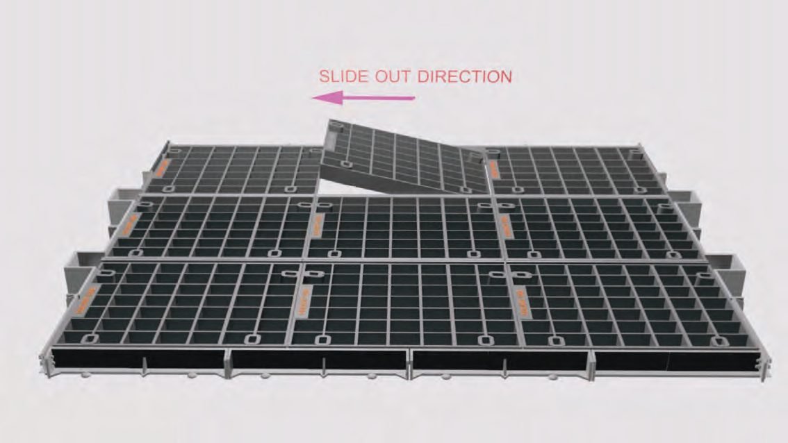
  1. Clean and remove any debris from the cover sides and seating areas.
  2. Drop the covers into the frame in the correct orientation, starting with one row in the middle — refer to the slope on the frame side and the matching slope on the cover.
  3. Place the covers at the end rows next, then fill in the remaining covers.
  4. After each set of covers is placed, adjust the levelling bolts on the frame and I-beam holder if required.
  5. Check the covers sit well, with metal-to-metal contact against the frame, and do not rock when walked over.
  6. Check alignment — no gaps between cover and frame, or between adjacent covers.
  7. Retighten all frame coupling bolts. Light tapping on the I-beams and frame parts may be needed for final alignment.

Shuttering

  1. Remove some covers and place the shuttering inside the perimeter of the pit.
  2. Set the shuttering approximately 10 mm higher than the bottom of the frame.
  3. Replace all covers and confirm alignment without gaps between cover and frame or cover and cover.
  4. Mask all keyways in the covers.
  5. Tighten the loosely pre-fastened I-beam holder lid into the I-beam.

Concreting

  1. Pour concrete — C45 grade preferred — between the frames until it reaches the shuttering, and tamp to avoid voids.
  2. Pour concrete into the integrated L-angle gap until it reaches the I-beam holder lid, and tamp.
  3. Fill concrete into the I-beam holder lid.
  4. On recessed covers, pour the concrete infill onto the covers.

Application of grease

  1. After the concrete has cured, remove the covers one at a time.
  2. Apply grease generously to the sides and seating portion of both cover and frame, then refix the cover.
Before you start
  • Always refer to the unit drawing for component identification.
  • Where anchoring of the frame unit is shown on the drawing, anchor as indicated.

Support

Need a hand on site?

Unit-specific installation drawings ship with every order, and Ayush Rewani can arrange installation assistance for larger multipart and trench systems.